
Vibe-coding hardware: Navigation Marks
Iterative development of PCBs and microcontrollers with AI
Having had some success using AI to develop software, firmware and as a delegated sysadmin, I was curious to see what it could do with hardware. My weapon-of-choice for this is OpenAI’s Codex CLI but I also use other models, including Anthropic’s Claude models, to do similar things at work.
What are navigation marks?
As you (probably) know by now, I like boats. Seas and rivers use various navigation marks to help keep sailors safe and pointing in the right direction, and their shapes and lights are standardized by an international body called IALA.
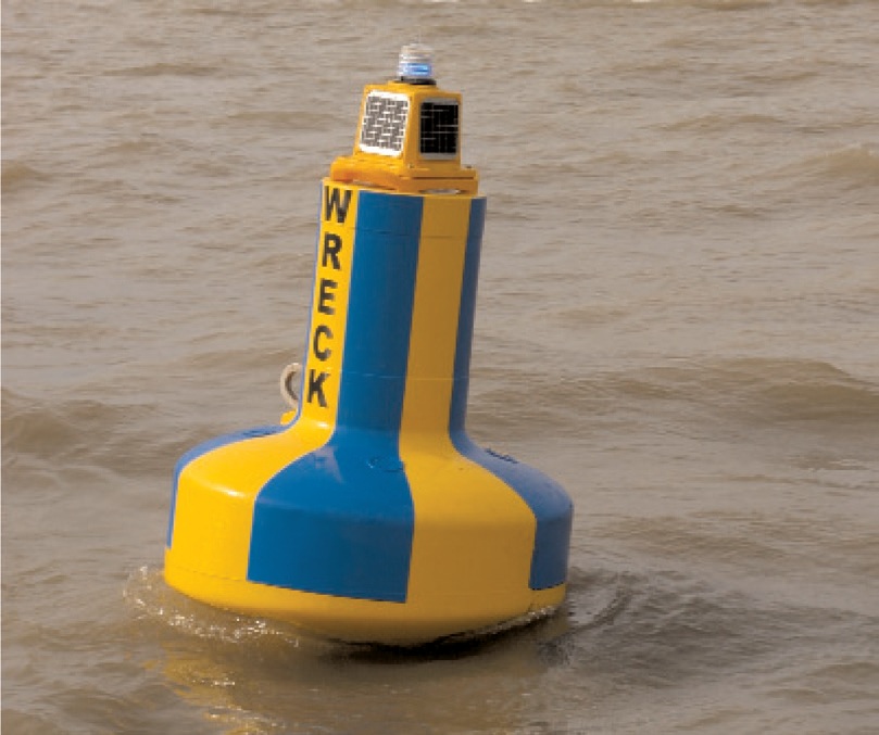
Some of the most-common ones are the red and green markers that define the edge of a navigable channel: the nautical version of the painted lines that mark the edge of a road. These can be floating buoys or fixed poles, but the shapes and colors are the same.
If you’re sailing into a port in Europe then you keep the red ones on your left and the green ones on your right, and the reverse as you sail out. This standard is called IALA-A.
In America it’s the exact opposite.

This accident-waiting-to-happen for sleep-deprived transatlantic sailors is called IALA-B. American sailors learn “red right returning” which, I guess, is easy to remember. At least they keep the shapes the same: cylindrical “cans” on the left going in and conical “cones” or “nuns” on the right. I have no idea why they call them nuns, they just do. I learnt to sail in Europe but now I live in America, so I have to remind myself of this every time I get on the water. I’m also learning to pronounce buoy as the American “boo-ee” instead of the British “boy”. Don’t get me started on meters and feet.

That’s fine when you can see the colors and shapes, but what happens when it gets dark? That’s where the lights come in. These navigation marks usually have colored lights on them that flash a distinctive pattern so you can recognize them at night. This is a sample from a NOAA chart (only landlubbers call them “maps”):
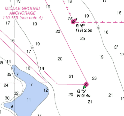
This American chart shows water depths in feet (the black numbers) and two of these navigation buoys. The top one is labelled R “6” Fl R 2.5s which translates as “a red buoy with the number 6 painted on it that flashes a red light once every 2.5 seconds”. The bottom one is a green buoy numbered 5 that flashes a green light every 4 seconds. If you can see those flashing lights then you can find your way up the navigable channel.
So what’s all this got to do with iterative AI-developed hardware?
Up the creek without a paddle

As you may recall from my tide gauge experiment, my nearest waterfront (well… swampfront) is at the top of a shallow creek. I’d like to keep a boat there because I’m stubborn. I therefore need to navigate up the narrow winding deep bit to avoid getting stuck on the shallow muddy bits, but it all looks like a flat expanse of water from the surface. This is exactly why those navigation marks were invented!
Now, quick disclaimer: don’t just go sticking flashing lights in your nearest river. In the US, “navigable waters” are governed by the US Coast Guard and they generally decide where these things go (Title 33 of the Code of Federal Regulations, in case you’re interested) to prevent a confusing chaos of private lights and shapes, and waterways in other countries are governed by equivalent bodies. Luckily, the top of my local creek is not classed as “navigable” so only a fool would try and take a boat up there, I am on good terms with the landowner, and I can therefore put some sticks in the water to mark the edges of the deep bit without upsetting anyone. People have been doing this for thousands of years: in Britain they’re called withies. I can then put small solar-powered flashing lights on top of these sticks so I can still see them when it starts to get dark. In keeping with the spirit of IALA, I will 3D print small housings for these lights which I will make can/cone shaped and paint the appropriate color.
Attempt one: modified garden lights
I have lots of these cheap solar-powered garden lights and, because my wife keeps obliterating them with the strimmer, I have a lot of broken ones to use for spare parts.
These lights are very simple: a small PV cell charges a AAA NiMH battery by day, and at night the battery powers a white LED. So all I want to do is to replace the white LED with a red or green one, and make it flash a programmed pattern.
Actually, not so simple. I’ll want a basic microcontroller to control the flash pattern and the joule-thief arrangement of the white LED won’t power that. So I’ll want a boost converter to bump the battery output up to 5V and some other components to connect it all together.
Codex helped me design the circuit, which I built (very badly) on some prototyping board.
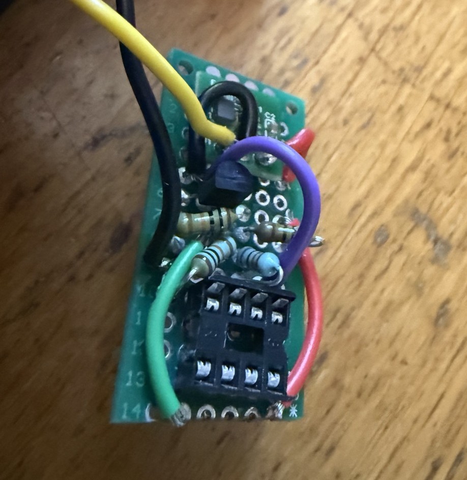
By the time I’d finished making horrible snail-trails of solder on the back to join up the components I figured this would be much easier on a PCB.
I have absolutely no experience of PCB design, so I gave Codex a go.
Attempt two: garden light with PCB
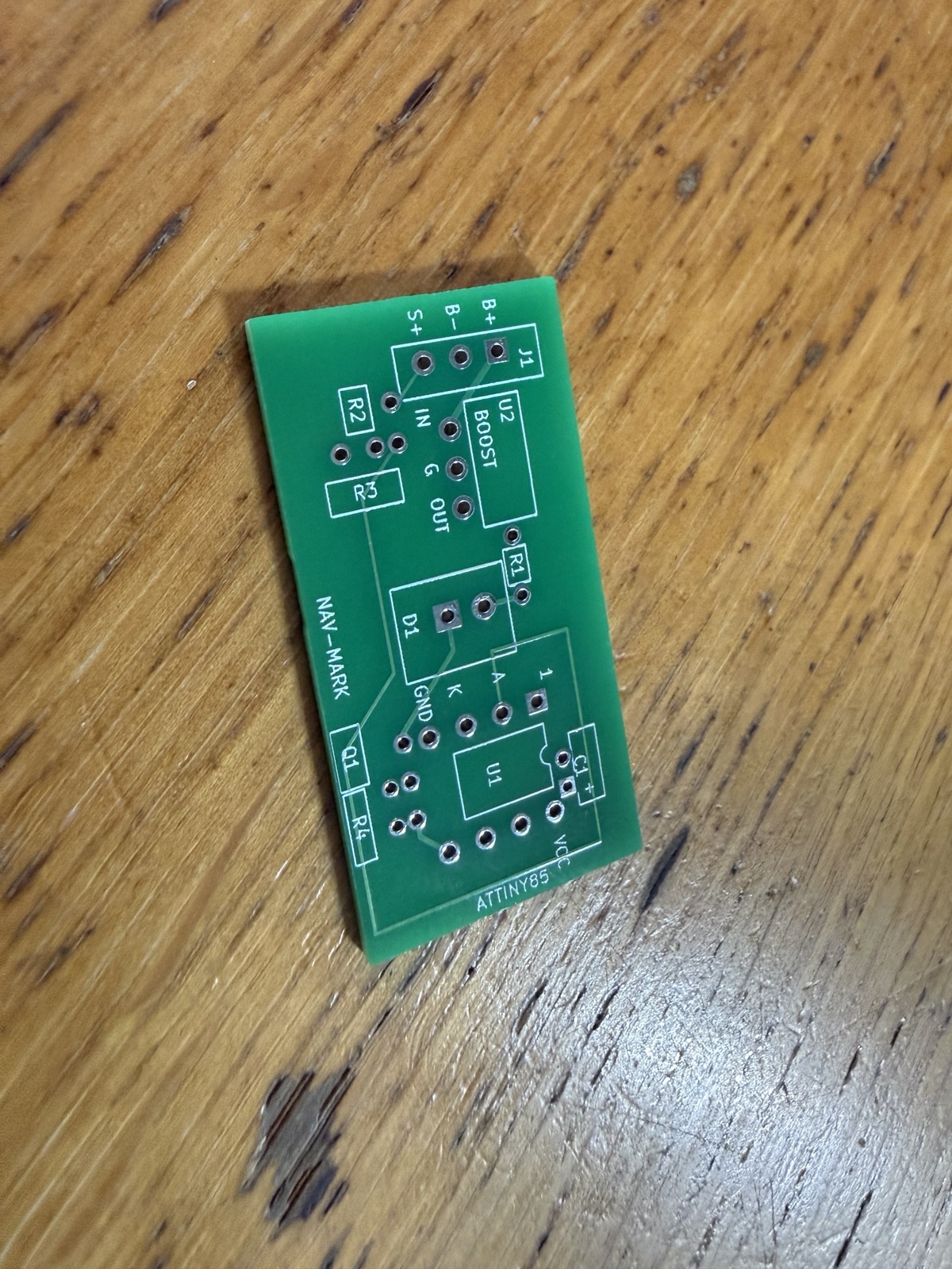
There are companies in China that will send you a working prototype before their US equivalent has replied your email requesting a quote. That’s not a great state of affairs, but this isn’t a geopolitics blog. One such company making PCBs is called JLCPCB and I was utterly astounded at how cheap and easy this was. I uploaded the design files that Codex spat out to their website and ordered 10 custom PCBs. Total price including delivery: $4.71. That is not a typo - for less than $5 I had ten 2-layer PCBs of my own unique design manufactured in China and sitting on my doormat.
Here’s one of them:
Let’s solder on the components:
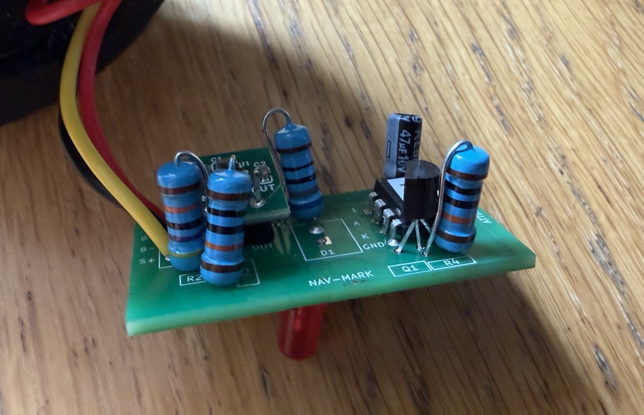
That’s much neater than what I had before but, to be honest, the design is a bit rubbish: the components are too close together, I’ve had to mount my resistors vertically to make them fit, the legs of a transistor cross each other, the silkscreen labels are a bit random… but IT WORKS!
So with a bit of AI, the price of one beer and some soldering I have a working circuit controlling a flashing light. I’m impressed.
Unfortunately, it doesn’t last very long. All those new electronics drain the battery faster than the PV can top it up.
Attempt three: GPT-5.6 Sol
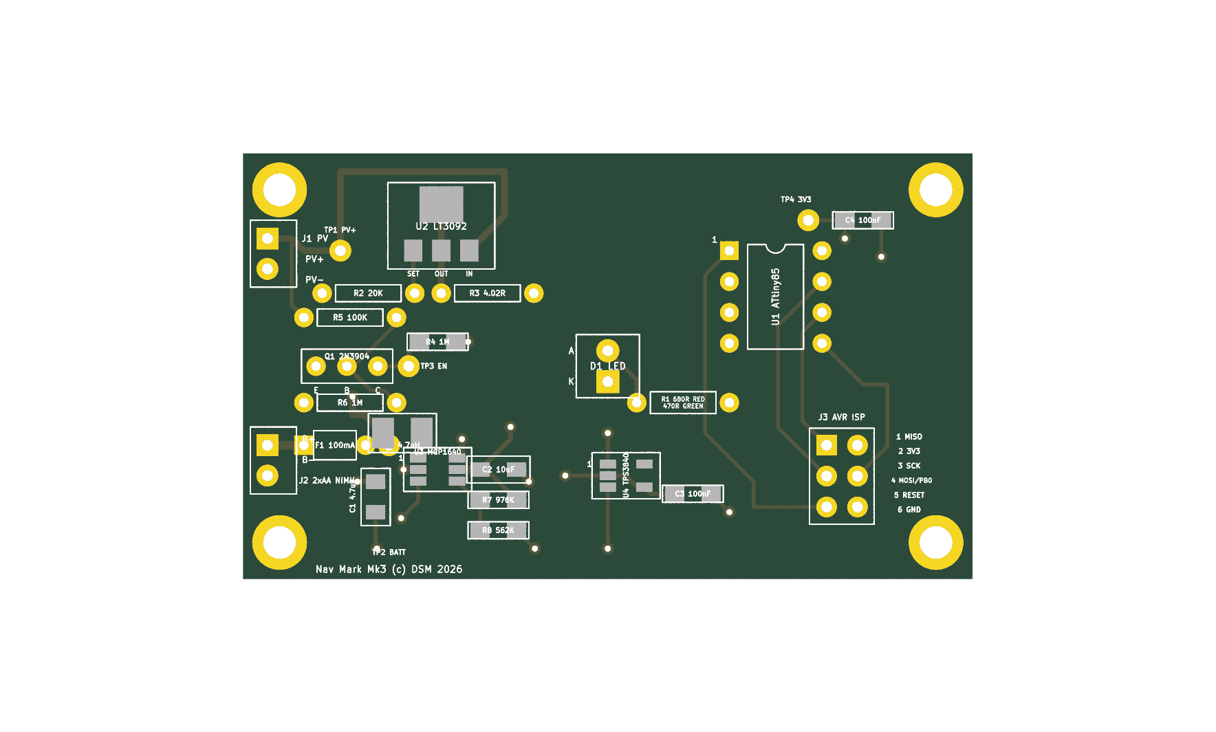
At about this time, OpenAI released their GPT-5.6 family and it’s considerably smarter than what preceded it. I used Sol, the thinkiest(?) version to start again and build me a new design. This one uses a pair of AA batteries instead of a single AAA, a larger PV and a much-improved PCB.
I haven’t ordered the new PCBs yet, but here is a preview made for me by Codex:
I’ll put all the designs, code and 3D shapes on my GitHub soon.